Using External Stepper Drivers

The boards are so simple, I don't want to raise the price and lead time by getting them assembled.
Assemble as shown. It is easiest if you solder the 3 pin connector before the 8 pin connectors.

Most external drivers use opto isolation for the step, direction and enable signals. Those typically require 5V. Some will also operate on 3.3V, but for best performance, they should be operated at 5V. The 6 Pack controller uses I2S drivers for those signals and can output 3.3V or 5V. This is selected by putting the Vcc jumper (center of controller) on the 5V side.
Note: The 5V power is derived from the controller's main power input terminal block, so that must always be on when in use, even if the ESP32 is power via USB.

This will cause all step, direction and enable signals going to the stepper drivers to be 5V. It also affects the SPI CS signal to be 5V, but that is not used with external drivers. The I2SO(24) through I2SO(27) pins on CNC I/O Module #5 will also be 5V.
- Place all 3 MS/SPI jumpers on the MS side.
- Place the TMC5160 jumper on the default side.

You can manually wire the drivers to the sockets. Here are the pinouts for the sockets.

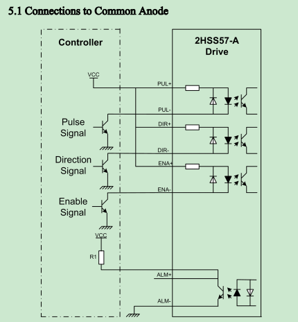
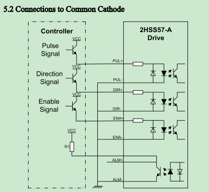
You can use adapter boards that re-route the signals to the terminal blocks. The drivers will operate with a common signal going to the negative side (default) of the optos or the positive side. Set the jumper on the adapter board for your choice for the common signal (Vcc or Gnd).

Wire to the external driver per below. You will have to daisy chain the common signal.

Common ground wiring is shown in the image below. Notice the common wire (black) loops through all the (-) sides of the signals.

Many drivers that use opto isolators require an inverted signal. This is because the optos invert the signal. There are 2 ways to do this on most drivers.
You can invert the step and direction pulses with the $Stepper/StepInvert=XYZABC setting (set only the letters you want inverted. The direction signal can also be inverted with $Stepper/DirInvert=XYZABC.
A second, and possibly better, way it to change the wiring from common cathode (-) to common anode (+).
You can mix external drivers and standard StepStick style drivers, but you should not use Trinamic SPI type drivers. They send signals back to the ESP32 and the ESP32 is not compatible with the 5V Vcc setting.
If you must use Trinamic and external drivers you can use these drivers with a level shifter. Set the logic voltage at 3.3V.