A man-in-the-middle program for Arduino/ESP32/ESP8266 that lets you control Mitsubishi Heavy Industries heat pumps/air conditioning systems that use the wired RC-E1 controller (3 wires).
MHI models from around 2004-2006 (series FDTA, FDUA, FDTCA, FDKNA, FDURA, FDENA) should all be compatible with this controller. I only tested this with an FDURA301R, though.
A talk about this project can be found in YouTube: https://www.youtube.com/watch?v=HfyPsXzC8Es
The RC-EC1 controller and your I/U (indoor AC unit) communicate by sending 16-byte-long UART packets at 1200 bauds with 1 even partiy bit through the data line that connects the two devices, roughly once per second. The same data line is used bidirectionally. The flow is: the controller sends the desired state, ~150ms later the I/U responds with some confirmation data that I haven't fully reverse engineered, and again the controller responds with an ACK that repeats most of the state from the first packet. All packets are 16 byte long and the last one is a Sum of Bytes % 256 checksum.
This program works by reading the packets from one end of the data line and writing them on the other end in real time, while optionally modifying them in transit to change the setpoint temperature, mode, fan speed or on/off status. This program can't create new packets, only modify the existing ones. My unit doesn't have louver nor grill options, so I didn't reverse engineer those.
There's one caveat: The wired controller won't know about the new state set by this, so it won't reflect it on the display. There is some logic in this code, though, to revert to the state set by the controller if any of it changes (ie: if you change the settings using the wired controller, they take precedence).
Software is soft, hardware is hard.
There are three wires between your I/U machine and your RC-E1 controller. Two of them are power and one is data (which is used bidirectionally). You will have to identify which one is which on your controller. This expects to be connected beetween the two ends of the data wire. HOWEVER, Mitsubishi's data cables use 12V, while the ESP32 uses 3.3V and Arduino uses 5V, so you will need two bidrectional logic level converters between the two pins on your ESP/Arduino and the data cables that go to your I/U and your RC-E1.
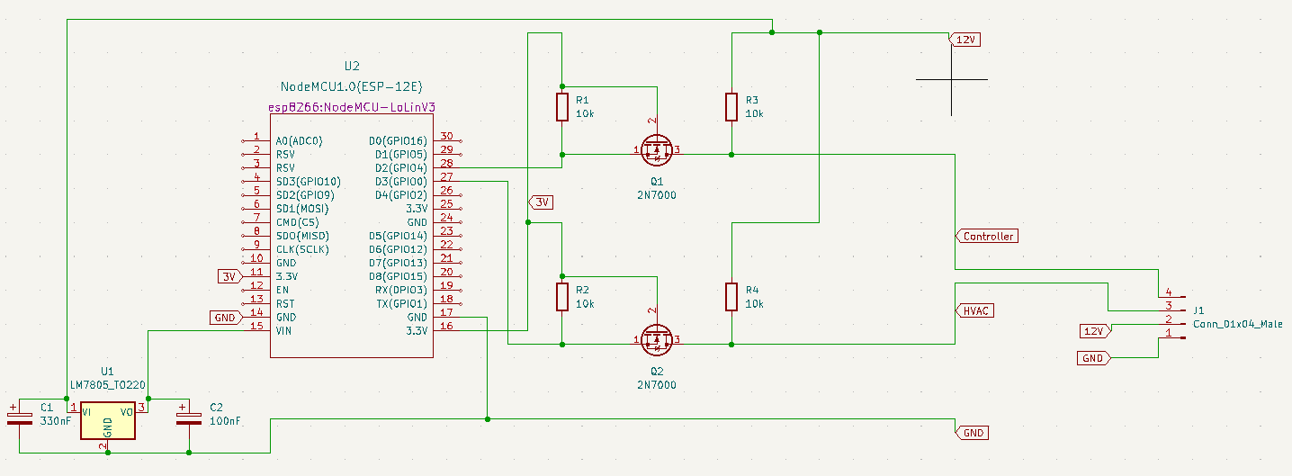
A full schematic using an ESP8622, two logic level converters and a power regulator to power the ESP8622 from the 12V power line coming from the I/U would look like this:
I hope you don't break your AC while trying to hook this :D
I'm using this code together with a proprietary IoT platform that runs on ESP32 to connect the board to the internet via WiFi and control my AC from my phone, through voice assistants, etc. but I've decided not to make that part open source because I don't want to encourage the use of any specific proprietary platform
It should be trivial to extend this code to integrate it with any remote or local controller of your choice. The globals you want to read/write to interact with your MHI AC are called myOnOff, myTemperature, myFanSpeed and myMode.